Thursday 30 October 2014

Posted by Unknown | 23:39 | 1 comment
This is my first of five posts in this microcontroller tutorial series. Throughout this tutorial, I will be building a microcontroller circuit while documenting the process. By following what I do, you can make your own at home.
My goal is to make a circuit that is as simple as possible, and which requires no external programmers or debuggers. You should be able to just plug it into a USB port on your computer and program it.I have not planned this out in any way. I am just going to build it, and write about the process. Hopefully we’ll end up with a usable circuit.
In this first part of the microcontroller tutorial, I’ll start from scratch. I want to explain what a microcontroller is, in very simple terms. I want to get everyone on board, before we dive into making the circuit. 

What Is A Microcontroller?

You can think of a microcontroller like a tiny computer. You can connect things, like a small display, some buttons, a motor and some sensors. And you can put programs onto it and run them.
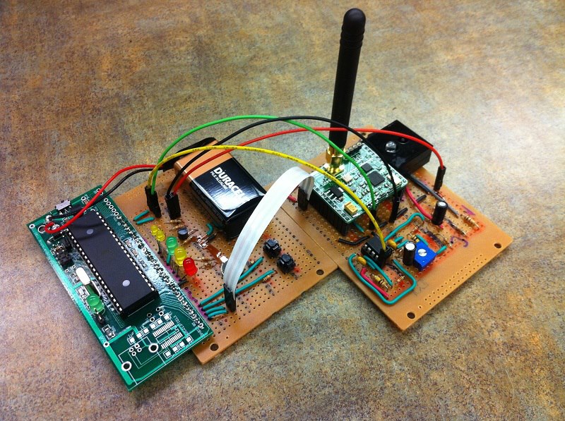
A microcontroller is an integrated circuit, and it can look like this:
But it can also have many other shapes and forms.

What Can You Do With A Microcontroller?

Oh, where do I begin?
There are so many things you can do with a microcontroller.
You could build a robot. Or an MP3-player. Or a cellphone. Or a door-lock that unlocks your door automatically when you enter a code on your smart phone.
The possibilities are endless!
Let’s say you want to build a robot. You can connect an infrared sensor to use as vision for the robot. And you can connect a motor with some wheels to make it move.
Now, all you have to do is to make a program that reads from the infrared sensor and controls the motor. In your code, you can make sure the robot stops if it sees something in front of it, and make it turn to either left or right before continuing.
When you know how to build microcontroller circuits, there are almost no limits to what you can do! And by following this microcontroller tutorial, you will learn to use microcontrollers in your own projects =)

A Closer Look At A Microcontroller :

The microcontroller doesn’t do anything by itself. You need to tell it what to do, by making a program that you load into it to it. This is often called programming the microcontroller.
From the program you write, you can control the input and output pins.
So – by connecting something, such as a Light-Emitting Diode (LED) to an output pin, you will be able to switch the light on and off from your program.
An input pin could be used to check if a button connected to it has been pushed. Or to read the temperature from a temperature sensor.
In your program, you will be able to make decisions based on the input. So you can make a program that will start to blink a light if the temperature goes above or under a certain level. Put this into your beer-brewing room and you will get a visual alarm if the temperature for brewing is not right.

Programming a Microcontroller

Programming a microcontroller can seem a bit tricky because there are many confusing choices to make. I remember how I felt in the beginning. With all the available compilers, IDE’s, programmers and programming methods – no wonder you get confused!
So, let’s break it down.
These are the three steps necessary to program a microcontroller:
1. Write code
2. Compile your code to machine code
3. Upload the machine code to your microcontroller
What exactly to do at each step varies from microcontroller to microcontroller. But don’t worry – I’ll be guiding you through the exact steps needed when we get there.

Next Up In The Microcontroller Tutorial

It’s time to find a microcontroller and get to work. Finding a microcontroller isn’t necessarily as easy as you would like it to be. There are probably 58 billion different ones. Ok, maybe a little less. But a lot.
But I have some tips up my sleeve that will make it easier. But more on that in the next part of the microcontroller tutorial.
Throughout the tutorial, I will show you the steps you need to take to build your very own microcontroller circuit. You will then be able to use this circuit to build a blinking lamp, a robot or some other idea of your own.

Tuesday 28 October 2014

Posted by Unknown | 20:05 | No comments

Saturday 25 October 2014

Posted by Unknown | 20:13 | No comments
Always, people want to steal the passwords of their friends. Now, I want to discuss about the trick that, how to get the passwords of our friends memory card?
are you ready ? Yeah here are the steps....

Steps :

1. Download and install FExplorer.
2. Insert memory card into your phone. But don't access it through your phone.
3. Run FExplorer and open the path C:System. Then you will find a file name as          mmcstore. Move this file ( mmcstore ) into another location as you wish. And        rename the file name as mmcstore.txt.
4. Open that file ( mmcstore.txt ) in your phone or open in your PC and open the f      file in notepad.
5. Now you can see the password of your friends memory card.

Leave your comments. As it is working or not or is there anything to provide from me.

Friday 17 October 2014

Posted by Unknown | 20:17 | No comments
An electronic oscillator is an electronic circuit that produces a periodic, oscillating electronic signal, often a sine wave or a square wave. Oscillators convert direct current (DC) from a power supply to an alternating current signal.
Energy needs to move back and forth from one form to another for an oscillator to work. You can make a very simple oscillator by connecting a capacitor and an inductor together. We know that both capacitors and inductors store energy. A capacitor stores energy in the form of an electrostatic field, while an inductor uses a magnetic field.
Imagine the following circuit:
If you charge up the capacitor with a battery and then insert the inductor into the circuit, here's what will happen:
• The capacitor will start to discharge through the inductor. As it does, the inductor will create a magnetic field.
• Once the capacitor discharges, the inductor will try to keep the current in the circuit moving, so it will charge up the other plate of the capacitor.
• Once the inductor's field collapses, the capacitor has been recharged (but with the opposite polarity), so it discharges again through the inductor.
This oscillation will continue until the circuit runs out of energy due to resistance in the wire. It will oscillate at a frequency that depends on the size of the inductor and the capacitor.

Sunday 12 October 2014

Posted by Unknown | 20:02 | No comments
the the level of any conductive non corrosive liquids can be measured using this circuit. The circuit is based on 5 transistor switches. Each transistor is switched on to drive the corresponding LED , when its base is supplied with current through the water through the electrode probes.
One electrode probe is (F) with 6V AC is placed at the bottom of tank. Next probes are placed step by step above the bottom probe. When water is rising the base of each transistor gets electrical connection to 6V AC through water and the corresponding probe. Which in turn makes the transistors conduct to glow LED and indicate the level of water. The ends of probes are connected to corresponding points in the circuit as shown in circuit diagram.Insulated Aluminum wires with end insulation removed will do for the probe. Arrange the probes in order on a PVC pipe according to the depth and immerse it in the tank.AC voltage is use to prevent electrolysis at the probes. So this setup will last really long. I guarantee at least a 2 years of maintenance free operation. That’s what I got and is still going.
                                                     
                                                              Components:
T1 – T5 BC 548 or 2N2222 Transistors
R1-R5 2.2K 1/4 W Resistors
R6-R10 22K 1/4 W Resistors
D1 – D5 LED’s ( color your choice)

Saturday 11 October 2014

Posted by Unknown | 19:35 | No comments
Spell Check is Very Easy Now, smart pen that vibrates when you make spelling Error - New Technology Gadget

German inventors have developed a new hi-tech pen that gently vibrates every time it senses a spelling mistake or sloppy handwriting. 
Lernstift is a regular pen with real ink, but inside is a special motion sensor and a small battery-powered Linux computer with a WiFi chip. 
Together those parts allow the pen to recognise specific movements, letter shapes and know a wide assortment of words. If it senses bad letter formation or messy handwriting, it will vibrate, 'ABC News' reported.
Users can choose between two functions: Calligraphy Mode - pointing out flaws of form and legibility or Orthography Mode - recognising words and comparing the word to a language database. If the word isn't recognised it will vibrate, according to Daniel Kaesmacher, the 33-year-old co-founder of Lernstift from Munich.
The other co-founder Falk Wolsky, 36, had the idea for the pen last year while his 10-year-old son was doing his homework.
"His son had been struggling with his work and staying focused and Falk thought there should be a pen that gives him some sort of signal so he stays focused," Kaesmacher said.
After a year and a half in development, the founders have now brought Lernstift to Kickstarter to begin raising money and gauging interest.

Friday 3 October 2014

Posted by Unknown | 20:18 | No comments

Thursday 2 October 2014

Posted by Unknown | 05:36 | No comments
The purpose of the transistor tester circuit is to test the NPN or PNP transistor whether they are working fine or not.So,i decided to provide you the simplest circuit that can be built on breadboard.I think this is the most simplest circuit ever to test the transistor and it works fine.You just need to place the transistor to check it and press the button.That’s all.If LED blinks by pressing the button your transistor is not faulty.

 --> The circuit consists of few resistors,LED and buzzer.There are two circuits.One to check NPN transistor and the other to check PNP transistor
As you know transistor can also work as a switch.Here this property of transistor is used to check the transistor.If we see the NPN transistor tester,the base pin is connected to button via series resistor of 10k. The button when pushed connects the two points and the voltage (3V) reaches the base pin of NPN transistor (that needs to be checked).10k resistor simply reduces the base current.Transistor gets ON when button is pushed (if the transistor is not faulty) and the LED will glow and the buzzer makes sound. "If transistor is faulty then LED
will not glow on pushing the button or LED will glow without pushing the button".....!!!!!!!
The principle of PNP transistor tester is same as the NPN transistor tester.The difference is just the placement of components.As PNP transistor turns ON when its base voltage is less than 0.6V. So,By pushing the button,PNP transistor (that needs to be checked) turns ON and LED glows as well as buzzer.The whole circuit uses only one supply that can be provided to the circuit using 3V cell.                                                                                                                      

Components:

R1,R3 270 ohm (1/4watt)
R2,R4 10k (1/4watt)
D1,D2 LED (green)
BZ1,BZ2 buzzer
Push Button x 2

Note:


"If transistor is faulty then LED will not glow on pushing the button or LED will glow without pushing the button  "

Bookmark Us

Delicious Digg Facebook Favorites More Stumbleupon Twitter