Saturday, 21 February 2015

Posted by Unknown | 19:17 | No comments

Introduction

Usually embedded systems are complex design which include multiple peripherals interconnected like LED, LCD, RTC, other microcontroller, Memory card, etc with main computer or master to expand its capabilities. All these peripheral’s interfacing is done by standard rules which is called protocol. Protocol is a set of rules that defines how communication between systems and devices are done which include bit ordering, bit pattern meanings, creating data frames, error checking, etc. UART, SPI, I2C, USB and Ethernet are some of the protocols widely used in embedded systems for serial data communication. Here we are bound to I2C Protocol.
                 The Inter-integrated Circuit (I2C) Protocol was originally developed in 1982 by Philips(now known as NXP) used to connect multiple devices with only two wire. Its is also called two wire interface protocol.
Why I2C Protocol ?
Comparing I2C with UART


  • In UART, separate clock line is not used with data transmission so both device should agree on same Baud-rate. If differences occur between Baud-rate on either end will cause garbled data while in I2C separate clock line is used.
    • UART uses hardware overheads like start bit, stop bit, partiy bit or CRC bit in each frame of transmission which will lead to increase in transmission time while I2C use only acknowledgement bit(ACK) or no acknowledgement bit.
    • Another drawback of UART is that they are suited to communications between two, and only two, devices while I2C can used with multiple devices and different modes like multi-master or single master, etc.
    • Data transfer speed is also an issue for UART, they are limited to some extent and maximum baud-rate is around 230400 bps.
    Comparing I2C with SPI


    • The first drawback of SPI is pin used to connect multiple devices. If we connect two device with SPI standard it will use four pins MISO, MOSI, SCK, CS.
    • In SPI protocol, there is only single master but it can support arbitrary number of slaves. While in I2C, multiple master can be possible.
    • If we compare data transmission speed of SPI and I2C, then SPI will win definitely. SPI support speed upto 10MHz (10 Mbps).

    What’s good in I2C ?

    • I2C requires only two line(two wire), but those two wires can support up to 1008 slave devices.
    • Unlike SPI, I2C can support a multi-master system, allowing more than one master to communicate with all devices on the bus (although the master devices can’t talk to each other over the bus and must take turns using the bus lines).
    • Data rates of I2C devices can communicate at the rate of 100kHz to 400kHz.

    How I2C Protocol Works ?

    To understand the working of I2C Protocol, Let we take some practical examples
    Single Byte Transfer
                                                                     Single Byte Transaction
    • Idle condition: As you can see in above figure, at the initial condition SDA and SCL both High because of both line pulled High with pull-up resister.
    • Start condition: Data transfer is start when SDA line pulled down mean High to Low when SCL line is High.
    • Bit Detect: Slave can understand bit reception when it receives single bit ‘1’ or ‘0’ when SCL line is High. 
    • Data allowed to change: Transition of bit from 1 to 0 or 0 to 1 is only allowed when SCL line is Low as seen in pick.
    • ACK Bit: Transmitter must release the SDA line after transmitting 8 bit to allow the Receiver to pull SDA line Low to acknowledgement the previous 8 bit data reception.
    • Stop condition: is only understood when SDA line goes Low to High while SCL line is High.
    Note: In I2C Protocol Byte is transmitted MSB to LSB. And in multi-Byte transmission, every 8 bits has a 9th bit that is an acknowledge.
    Write/Read Two Byte  from Master to Slave

    Start Condition
    Every communication in I2C Protocol is begin with start condition which we already studied above how start condition form. This alerts all slave devices that a transmission is about to start.
    Address Frame Byte
    The address frame byte include device address which is of 7-bit long and Read(1)/Write(0) bit.  The address frame byte is always sent first when any new communication sequence initiate.
    ACK/NACK Bit
    The 9th bit of the frame is the NACK/ACK bit(here NA or A). This is the case for all frames (data or address). Once the first 8 bits of the frame are sent, the receiving device is given control over SDA. If the receiving device does not pull the SDA line low before the 9th clock pulse, it can be inferred that the receiving device either did not receive the data or some error occur. 
    Data Bytes
    After the address frame byte has been sent, data bytes can begin being transmitted. The master will simply continue generating clock pulses at a regular interval, and the data will be placed on SDA by either the master or the slave, depending on whether the R/W bit indicated a read or write operation. The number of data byte is arbitrary, and most slave devices will auto-increment the internal register, meaning that subsequent reads or writes will come from the next register in line.
    Stop condition
    Every communication in I2C Protocol is end with stop condition which we already studied above. During normal data writing operation, the value on SDA should not change when SCL is high, to avoid false stop conditions.

    Speed of I2C Protocol

    Common I²C bus speeds are the 100 kbit/s standard mode and the 10 kbit/s low-speed mode, but arbitrarily low clock frequencies are also allowed. Recent revisions of I²C can run at faster speeds typically 400 kbit/s Fast mode, 1 Mbit/s Fast mode plus or Fm+, and 3.4 Mbit/s High Speed mode.

    More About I2C Protocol

    10-bit Addressing suppor

    ts more number of devices
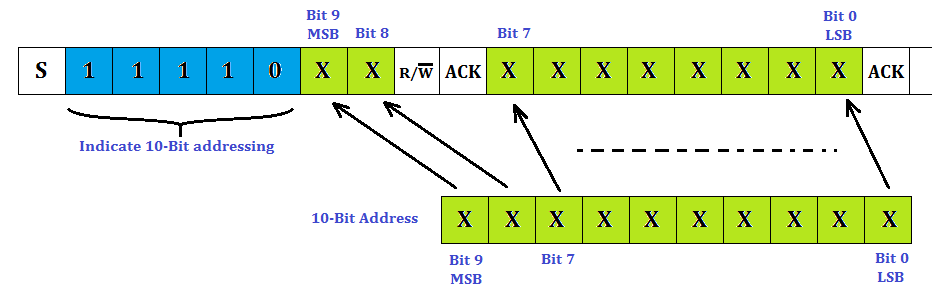
    In order to increase device address capability, 10-bit addressing scheme is introduced to I2C Protocol by which we can connect more number of devices by using I2C Protocol.


    In a 10-bit addressing system, two frames are required to transmit the slave address. The first frame will consist of the code 11110xyz, where ‘x’ is the MSB of the slave address, y is  8th bit of the slave address, and z is the Read/Write bit as seen above. The first frame’s ACK bit will be asserted by all slaves which match the first two bits of the address. As with a normal 7-bit transfer, another transfer begins immediately, and this transfer contains bit 0 to bit 7 of the address. At this point, the addressed slave should respond with an ACK bit. If it doesn’t, the failure mode is the same as a 7-bit system. 

    Clock stretching

    • In an I2C communication the master device determines the clock speed. However, there are situations where an I2C slave is not able to co-operate with the clock speed given by the master and needs to slow down a little. This is done by a mechanism referred to as clock stretching.
    • An I2C slave is stretching the clock by pull down the SCL if it needs to reduce the bus speed. The master on the other hand is required to read back the clock signal after releasing it to high state and wait until the line has actually gone high.

    Repeated Start Conditions

    • When we communicate through I2C bus, its obvious in most cases that first you need to send command and then you get response from slave, so each time you dont need to terminate communication by stop condition. You can use start condition reapetedly without terminating previous transaction. The I2C protocol defines a so-called repeated start condition.
    • For example, After having sent the address byte (address and read/write bit) the master may send any number of bytes followed by a stop condition. Instead of sending the stop condition it is also allowed to send another start condition again followed by an address (and of course including a read/write bit) and more data. This is defined recursively allowing any number of start conditions to be sent.
    • The purpose of this is to allow combined write/read operations to one or more devices without releasing the bus and thus with the guarantee that the operation is not interrupted.

    Thursday, 12 February 2015

    Posted by Unknown | 19:42 | No comments
    Don't get confused between JOB and studies, " Studies is to learn and job is to earn ". Once you fall behind money you may not be truly interested in learning. Its true that you can gain practical experience in job, but it depends on the type of company you are joining.
     Knowledge of B.E engineers v/s Knowledge of M.Tech engineers :
    My senior had to say this in comparison of B.E engineers v/s M.Tech Engineers,
    In my experience i have seen that, Graduate Engineers can make things work but they are not able to reason it how its working and why it didn't before. And, Masters can theoretically prove why the thing is not working, but they cant fix it".
    Starting career in a MNC (More Money, Less Knowledge) :
    If you join an MNC you may be working on some patch of hardware or software which is already developed by some senior guys. You may hardly get to touch the real thing. First one to two years, you will be doing more documenting work that designing and developing. MNC's follow strict designing guidelines and protocols where in you are hardly allowed to make mistakes. If you want to make money from start of your career then join an MNC. 
    Joining a startup (Less Money, More Knowledge) : 
    If you really want to learn doing a job then join a startup product development company, you will get huge exposure to everything that's going on in the company. You will go across everything, starting from hardware design to software development, testing, problems faced during the product development. And you will be doing everything here, if you develop the software, you are going to test it and if there are any issues , you are the one responsible to fix it. The initial growth and salary will be slow in a start-up but once you have acquired the knowledge here, there will be no limits to your growth. 
    My Suggestion : 
    I personally suggest that you go for higher studies if there is no burden of responsibilities on you. If you have to support your family you may have to do a job. Don't Worry, You will get to learn in both places.
    These are totally my personal opinions based on my experience.

    Sunday, 16 November 2014

    Posted by Unknown | 18:45 | No comments

    1.Why is the letter I used to represent current?

                    The letter I seems to be an odd choice for the English language, but it was chosen in the early days of electricity to represent intensity of current which we simply call current today. The unit of current, the ampere, is named after the French scientist André-Marie Ampère in recognition of his work on the relationship between electric current and magnetism. Ampère referred to electric current as "l'intensité du courant électrique", so I was a logical choice to represent intensité (intensity). I am grateful to Barry Caruth for suggesting a search of the internet for "Ampère" and "l'intensité du courant électrique" which returns many sites as evidence (most of them French) enabling me to answer this question with confidence. 

    2.What is a "short circuit"?

    A "short circuit" is a connection of very low resistance such as a wire (almost 0ohm) which provides a very easy path for current. Think of it as an electrical short-cut. It is normally used to describe a fault or accidental connection rather than a deliberate one. 
    For example: if the leads from a battery touch one another they create a very low resistance connection across the battery, so we say they have caused a short circuit across the battery. Current will flow through this short circuit rather than through the proper circuit. This stops the circuit working and it may cause a fire because the leads and battery will become hot with a large current flowing. 

    3.What does "open circuit" mean?

    "Open circuit" means no connection. It is usually used to describe a break in some part of a circuit which could be deliberate (such as a switch in the open or off position) or a fault (such as a broken wire or burnt out component). 

    4.My project has a resistor labelled 47, does that mean 47kohm?

    No, it means 47ohm which is a much smaller resistance. 47kohm would be shortened to 47k (or 47K). The ohm (ohm) symbol is often omitted from circuit diagrams and component layouts but the k (meaning kilo = 1000) will always be included if it is needed. 

    5.A project on another website lists a 10kW resistor! What does it mean?

    It almost certainly means a 10kohm resistor. This is a common error which occurs when the web page specifies a Greek font. If this font is not available on your computer you see the character in your standard font and it happens to be W which is the symbol for watt, the unit of power. I avoid the problem on this website by using a small image for ohm. In a few projects a low value resistor with a high power rating is required but the power will be something smaller like 5W, never 10kW which is more powerful than an electric heater! 

    6.Where can I buy heatproof cable to replace the ordinary cable on my soldering iron?

    Silicone heat resistant cable is sold in 1.5 metre lengths for exactly this purpose by Rapid Electronics, part number 85-0590 (look in the Soldering Equipment section). If you use another supplier make sure you buy 3-core mains flex with a current rating of 3A (the proper name for mains appliance leads is flex, not cable). Please note that to change over to the new flex you will need to borrow a second soldering iron! This is because the flex is soldered to the iron's element. Make sure that you connect the wires correctly in the iron and in the mains plug which should have a 3A fuse. 

    7.My soldering iron was supplied with a hook, do I really need to buy a stand as well?

    For safety you must buy (or make) a stand for your soldering iron. Please don't use the hook because it leaves exposed the very hot element and tip of the iron - it is too easy to accidentally touch them and burn yourself. If you can't afford to buy a stand you could try making your own with a spiral of stiff galvanised iron wire (a coat-hanger?) screwed to a block of wood. Ideally the stand should include a damp sponge for safely wiping the tip of the iron when it needs cleaning. 

    8. What component has a black stripe in the centre (it looks like a diode)?

    A small component about the size of a resistor or signal diode with a single black stripe in the centre is a zero-ohm resistor, it is really just a wire link. These components are used on commercial PCBs because they are easier for machines to handle than small pieces of wire. The single black stripe is logical because it means zero in the resistor colour code. Ordinary resistors have at least four stripes. Diodes have a single stripe near one end, not in the centre. 

    9.How do I choose a relay to use with one of our projects?


    The 555 timer IC used in many projects can supply current up to 200mA so it can power most relays directly. However, you must connect a signal diode (a 1N4148 for example) in parallel across the relay coil to protect the 555. Note that this diode is connected 'backwards' so that it will normally not conduct.

    10.I want to use a large number of LEDs, do I need a resistor for each one?

    No, you can usually connect a few LEDs of the same type in series and just use one resistor. The number of LEDs you can connect in series depends on the circuit's supply voltage. This arrangement has the advantage of reducing the total current required by the circuit. 

    If you wish to have several LEDs on at the same time it may be possible to connect them in series. This prolongs battery life by lighting several LEDs with the same current as just one LED.
    All the LEDs connected in series pass the same current so it is best if they are all the same type. The power supply must have sufficient voltage to provide about 2V for each LED (4V for blue and white) plus at least another 2V for the resistor. To work out a value for the resistor you must add up all the LED voltages and use this for VL.


    Example calculations: 

    A red, a yellow and a green LED in series need a supply voltage of at least 3 × 2V + 2V = 8V, so a 9V battery would be ideal. 
    VL = 2V + 2V + 2V = 6V (the three LED voltages added up). 
    If the supply voltage VS is 9V and the current I must be 15mA = 0.015A, 
    Resistor R = (VS - VL) / I = (9 - 6) / 0.015 = 3 / 0.015 = 200ohm
    so choose R = 220ohm (the nearest standard value which is greater).


    11.What is a Darlington pair?


    A Darlington pair is two transistors connected together so that the current amplified by the first is further amplified by the second transistor, giving a very high gain of 10000 or so. 

    12.What does 'sinking a current' mean?

    It means current is flowing into the output of an IC. This happens when the output is low (0V) if there is a device connected between the positive supply (+Vs) and the output. It is the opposite of sourcing a current which means current is flowing out of the output. Most IC outputs can both sink and source current. 

    13.Are 'time period' and 'time constant' the same thing?

    No, they have different meanings although both are time. Time period is the duration of a single pulse or the time for one cycle of a repeating electrical signal. Time constant is a property of a changing system, such as a capacitor charging and discharging. 

    14.What does 'SMD' mean?

    'SMD' means Surface Mount Device. SMDs are components with small pads instead of leads for their contacts. They are designed for soldering by machine onto specially designed PCBs and are not suitable for educational or hobby circuits constructed on breadboard or stripboard. Do not buy SMD components for your projects.

    15.I'm interested in electronics, where should I start?

    I suggest that you start with a few simple projects, learning how to solder and how to identify the common components. You will need some tools to construct the projects. It is best to buy kits to be sure you have the correct parts.
    Many people then want to start learning how the circuits work and maybe try designing their own, usually by adapting a published circuit. You can read through the study section of this website. At this stage it is worth buying a breadboard for trying out circuits without soldering so that changes can be easily made and the parts re-used. The 555 timer circuits are great for simple projects.


    Thursday, 30 October 2014

    Posted by Unknown | 23:39 | 1 comment
    This is my first of five posts in this microcontroller tutorial series. Throughout this tutorial, I will be building a microcontroller circuit while documenting the process. By following what I do, you can make your own at home.
    My goal is to make a circuit that is as simple as possible, and which requires no external programmers or debuggers. You should be able to just plug it into a USB port on your computer and program it.I have not planned this out in any way. I am just going to build it, and write about the process. Hopefully we’ll end up with a usable circuit.
    In this first part of the microcontroller tutorial, I’ll start from scratch. I want to explain what a microcontroller is, in very simple terms. I want to get everyone on board, before we dive into making the circuit. 

    What Is A Microcontroller?

    You can think of a microcontroller like a tiny computer. You can connect things, like a small display, some buttons, a motor and some sensors. And you can put programs onto it and run them.
    A microcontroller is an integrated circuit, and it can look like this:
    But it can also have many other shapes and forms.

    What Can You Do With A Microcontroller?

    Oh, where do I begin?
    There are so many things you can do with a microcontroller.
    You could build a robot. Or an MP3-player. Or a cellphone. Or a door-lock that unlocks your door automatically when you enter a code on your smart phone.
    The possibilities are endless!
    Let’s say you want to build a robot. You can connect an infrared sensor to use as vision for the robot. And you can connect a motor with some wheels to make it move.
    Now, all you have to do is to make a program that reads from the infrared sensor and controls the motor. In your code, you can make sure the robot stops if it sees something in front of it, and make it turn to either left or right before continuing.
    When you know how to build microcontroller circuits, there are almost no limits to what you can do! And by following this microcontroller tutorial, you will learn to use microcontrollers in your own projects =)

    A Closer Look At A Microcontroller :

    The microcontroller doesn’t do anything by itself. You need to tell it what to do, by making a program that you load into it to it. This is often called programming the microcontroller.
    From the program you write, you can control the input and output pins.
    So – by connecting something, such as a Light-Emitting Diode (LED) to an output pin, you will be able to switch the light on and off from your program.
    An input pin could be used to check if a button connected to it has been pushed. Or to read the temperature from a temperature sensor.
    In your program, you will be able to make decisions based on the input. So you can make a program that will start to blink a light if the temperature goes above or under a certain level. Put this into your beer-brewing room and you will get a visual alarm if the temperature for brewing is not right.

    Programming a Microcontroller

    Programming a microcontroller can seem a bit tricky because there are many confusing choices to make. I remember how I felt in the beginning. With all the available compilers, IDE’s, programmers and programming methods – no wonder you get confused!
    So, let’s break it down.
    These are the three steps necessary to program a microcontroller:
    1. Write code
    2. Compile your code to machine code
    3. Upload the machine code to your microcontroller
    What exactly to do at each step varies from microcontroller to microcontroller. But don’t worry – I’ll be guiding you through the exact steps needed when we get there.

    Next Up In The Microcontroller Tutorial

    It’s time to find a microcontroller and get to work. Finding a microcontroller isn’t necessarily as easy as you would like it to be. There are probably 58 billion different ones. Ok, maybe a little less. But a lot.
    But I have some tips up my sleeve that will make it easier. But more on that in the next part of the microcontroller tutorial.
    Throughout the tutorial, I will show you the steps you need to take to build your very own microcontroller circuit. You will then be able to use this circuit to build a blinking lamp, a robot or some other idea of your own.

    Tuesday, 28 October 2014

    Posted by Unknown | 20:05 | No comments

    Saturday, 25 October 2014

    Posted by Unknown | 20:13 | No comments
    Always, people want to steal the passwords of their friends. Now, I want to discuss about the trick that, how to get the passwords of our friends memory card?
    are you ready ? Yeah here are the steps....

    Steps :

    1. Download and install FExplorer.
    2. Insert memory card into your phone. But don't access it through your phone.
    3. Run FExplorer and open the path C:System. Then you will find a file name as          mmcstore. Move this file ( mmcstore ) into another location as you wish. And        rename the file name as mmcstore.txt.
    4. Open that file ( mmcstore.txt ) in your phone or open in your PC and open the f      file in notepad.
    5. Now you can see the password of your friends memory card.

    Leave your comments. As it is working or not or is there anything to provide from me.

    Friday, 17 October 2014

    Posted by Unknown | 20:17 | No comments
    An electronic oscillator is an electronic circuit that produces a periodic, oscillating electronic signal, often a sine wave or a square wave. Oscillators convert direct current (DC) from a power supply to an alternating current signal.
    Energy needs to move back and forth from one form to another for an oscillator to work. You can make a very simple oscillator by connecting a capacitor and an inductor together. We know that both capacitors and inductors store energy. A capacitor stores energy in the form of an electrostatic field, while an inductor uses a magnetic field.
    Imagine the following circuit:
    If you charge up the capacitor with a battery and then insert the inductor into the circuit, here's what will happen:
    • The capacitor will start to discharge through the inductor. As it does, the inductor will create a magnetic field.
    • Once the capacitor discharges, the inductor will try to keep the current in the circuit moving, so it will charge up the other plate of the capacitor.
    • Once the inductor's field collapses, the capacitor has been recharged (but with the opposite polarity), so it discharges again through the inductor.
    This oscillation will continue until the circuit runs out of energy due to resistance in the wire. It will oscillate at a frequency that depends on the size of the inductor and the capacitor.

    Bookmark Us

    Delicious Digg Facebook Favorites More Stumbleupon Twitter